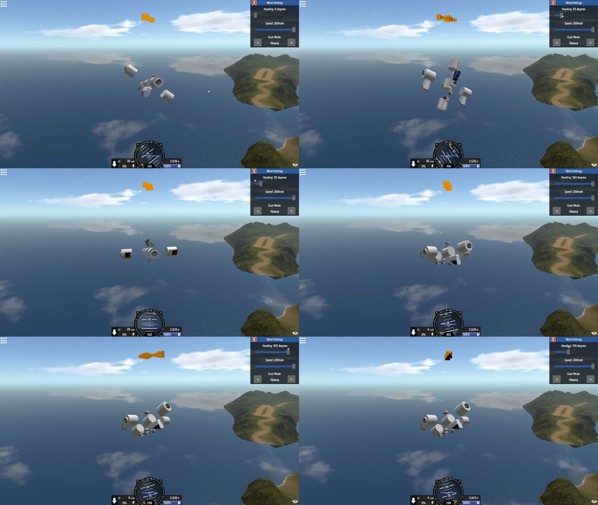
Lateral, longitudinal, and vertical velocities can be best described as sideways, forward/backward, and up/down speeds, respectively. These velocities are measured with respect to the aircraft, which is quite useful for use in a variety of flight systems. These velocity components have been re-derived in a fashion that does not include Angle of Attack (AoA) or Angle of Slip (AoS) data. As a result, these new formulae no longer depend on the assumption of absent wind (an assumption that was surprisingly valid for SP, but useless anywhere else).

Figure 0: A flight system successfully eliminates all aircraft velocity components
The velocity components were derived using rotation matrix methods. A coordinate system fixed on the aircraft was constructed using the columns of a modified pitch/yaw/roll rotation matrix. An inertial velocity vector, as measured from the ground, was then projected onto the aircraft-fixed coordinate system using dot product methods.
1. Code Snippets, Complete Code, and the Demonstrator
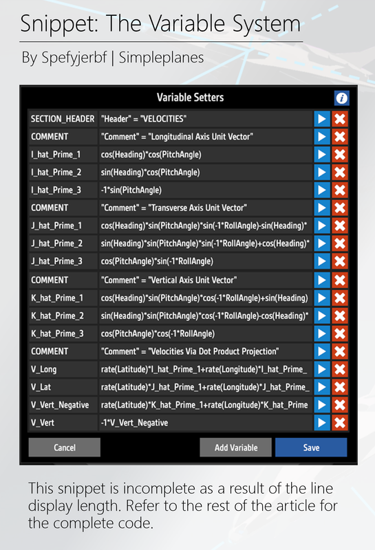
The necessary FT variable system to generate the aircraft's longitudinal (forward/backwards), lateral (sideways), and vertical (up/down) velocities is provided below:

Figure 1.1: Code Snippet
Note that the above snippet is incomplete, as some lines are too long to be shown. The complete variable system is included below for easy copy/pasting:
SECTION_HEADER: "Header" = "VELOCITIES"
COMMENT: "Comment" = "Longitudinal Axis Unit Vector"
I_hat_Prime_1: cos(Heading)*cos(PitchAngle)
I_hat_Prime_2: sin(Heading)*cos(PitchAngle)
I_hat_Prime_3: -1*sin(PitchAngle)
COMMENT: "Comment" = "Transverse Axis Unit Vector"
J_hat_Prime_1: cos(Heading)*sin(PitchAngle)*sin(-1*RollAngle)-sin(Heading)*cos(-1*RollAngle)
J_hat_Prime_2: sin(Heading)*sin(PitchAngle)*sin(-1*RollAngle)+cos(Heading)*cos(-1*RollAngle)
J_hat_Prime_3: cos(PitchAngle)*sin(-1*RollAngle)
COMMENT: "Comment" = "Vertical Axis Unit Vector"
K_hat_Prime_1: cos(Heading)*sin(PitchAngle)*cos(-1*RollAngle)+sin(Heading)*sin(-1*RollAngle)
K_hat_Prime_2: sin(Heading)*sin(PitchAngle)*cos(-1*RollAngle)-cos(Heading)*sin(-1*RollAngle)
K_hat_Prime_3: cos(PitchAngle)*cos(-1*RollAngle)
COMMENT: "Comment" = "Velocities Via Dot Product Projection"
V_Long: rate(Latitude)*I_hat_Prime_1+rate(Longitude)*I_hat_Prime_2+rate(-1*Altitude)*I_hat_Prime_3
V_Lat: rate(Latitude)*J_hat_Prime_1+rate(Longitude)*J_hat_Prime_2+rate(-1*Altitude)*J_hat_Prime_3
V_Vert_Negative: rate(Latitude)*K_hat_Prime_1+rate(Longitude)*K_hat_Prime_2+rate(-1*Altitude)*K_hat_Prime_3
V_Vert: -1*V_Vert_Negative
A demonstrator, pre-programmed with this variable system, is also available here. The longitudinal, lateral, and vertical velocities are defined as V_Long, V_Lat, and V_Vert, respectively. Note that the code has been commented by assigning a string (converted to a boolean) to a variable named COMMENT. While the code can be written as a single line for each velocity, it is recommended to use the code as it is currently written. Intermediate variables, such as the longitudinal, lateral, and vertical unit vectors, may be useful within a larger overall flight system implementation.
2. Limitations of Previous Flight Systems
Previous expressions for lateral, longitudinal, and vertical velocities were simple, but would fail under the presence of wind. These expressions used projection methods based wholly on trigonometry, with an argument related to AoA or AoS. With the condition of stagnant air, the total velocity could be easily decomposed into components using the described method.
The method, though, becomes invalid when wind is present. AoA and AoS, when wind is present, are functions of both the aircraft's velocity and the ambient wind conditions. Therefore, the lateral, longitudinal, and vertical velocity components fail with the presence of wind. A new expression, that does not use AoA or AoS angles, is needed to overcome this wind-related limitation.
3. The Mathematical Discussion
The lateral, longitudinal, and vertical velocity components can be found by projecting an inertial velocity vector onto the aircraft's principal axes. This section is, for purposes of this article, an explanation of this method. This discussion will most likely not be a complete mathematical derivation, but it will provide the necessary mathematical basis for the formulation of an aircraft's lateral, longitudinal, and vertical velocity components.
3.1 Constructing the Relevant Coordinate Systems
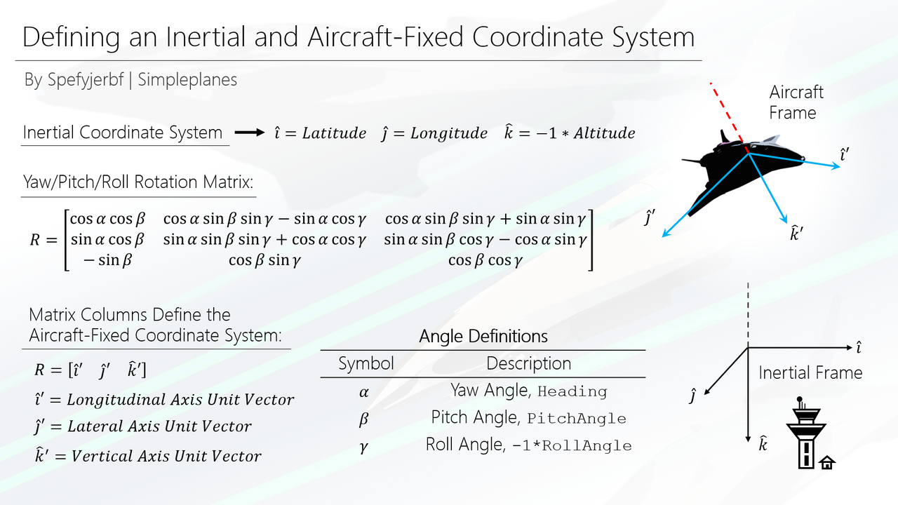
Two coordinate systems must be constructed to solve the velocity component problem. First, an inertial (ground-fixed) coordinate system is readily available with some manipulation. Latitude, Longitude, and Altitude information can be used to construct a left-hand coordinate frame, but a right-hand coordinate frame is necessary for successful vector projection. Therefore, the components of the inertial frame can be described as follows:
i = Direction of Latitude
j = Direction of Longitude
k = Down Direction
A particularly experienced reader may notice that this coordinate system is similar to a North-East-Down (NED) reference frame. Note that the inversion of the vertical axis will necessitate a similar sign inversion for the aircraft's roll angle.
The aircraft's longitudinal, lateral, and vertical unit vectors can be derived using a rotation matrix; the resulting axes are collectively referred to as the aircraft's principle axes. The columns of a standard yaw/pitch/roll rotation matrix define these principal axes within the scope of this velocity problem. Therefore, an aircraft-fixed coordinate system is defined using pitch, roll, and yaw angles, as shown below. Note that the new, rotated coordinate system is denoted by i', j', and k' unit vectors:

Figure 3.1.1 Defining the coordinate systems
3.2 A Component-Level Projection Method
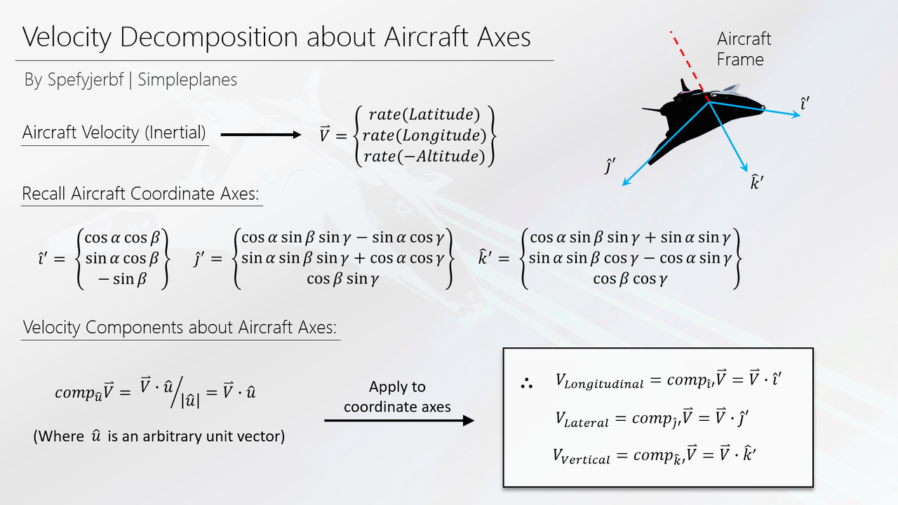
Four vectors of interest - each existing within 3D Cartesian Space - are available to complete a set of projection operations. The aircraft's velocity vector is available as measured from an inertial observer. Unit vectors representing the aircraft's lateral, longitudinal, and vertical axes are also available. The aircraft's lateral, longitudinal, and vertical velocities, then, can be found by projecting the velocity vector onto each of the aircraft's principal axes.
The chosen projection method produces the component of the velocity vector, along each principal axis. This operation is completed by dividing the dot product of the velocity and principal axis vectors, by the magnitude of the principal axis vector. The principal axis vectors, though, are unit vectors (magnitude of one). Therefore, the operation can be completed by simply taking the dot product of the velocity and principal axis vectors. The figure below illustrates the discussed methods, as well as their results:

Figure 3.2.1 Aircraft-fixed velocity components
The results of these operations are suitable for use within a flight system. However, the right-hand coordinate system, representing the aircraft's principal axes, is somewhat counterintuitive. The vertical velocity, as produced by the projection alone, is negative when the aircraft is moving upward. Therefore, the coordinate system has been re-converted into a left-hand system by, simply, multiplying the vertical velocity by negative one. Therefore, the vertical velocity, as provided within the FT code, will read as positive when the aircraft is moving upwards.

This post is for me to format forum posts and documentation before actually posting.
All below comments are from the old, recycled forum post.
@spefyjerbf Okay, thanks
@Joco80 I am still experiencing less downloads, but yeah, it is mostly a part count thing on the truck.
Back to what you said some time ago about downloads lowering, I have 15 upvotes on my truck and only 4 downloads... is that because of its size? It is a big drop
@EliteIndustries1 fixed