
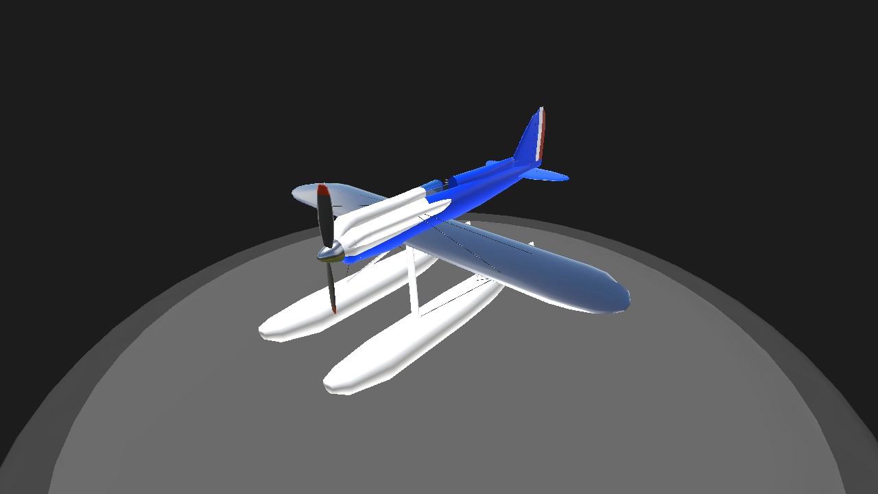
a simpler aircraft for the challenge of @apollo018364, here is a "brief" description from wikipedia.
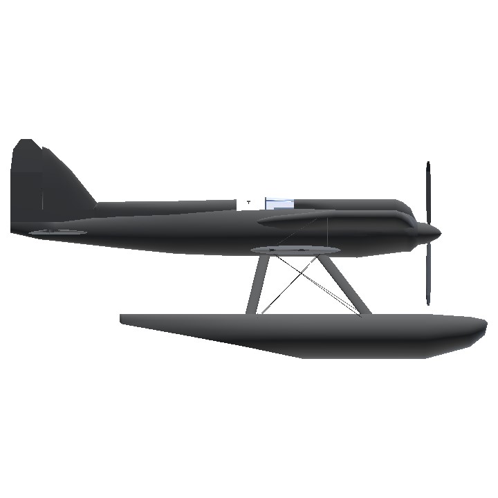
The Supermarine S.5 was designed by Reginald Mitchell for the 1927 Schneider Trophy. Following the earlier loss of the S.4 before the 1925 Schneider Trophy was held, Mitchell designed a new monoplane racer. Extensive changes were made between the S.4 and S.5, the principal goal of which was to achieve greater speeds. The design process was heavily influenced by wind tunnel testing, the resulting information from which was kept confidential for some time. The S.5 possessed a particularly low level of drag for a floatplane of the era. Furthermore, the resulting aircraft possessed numerous unorthodox features, some of which were developed to meet specific conditions encountered during high speed air races.
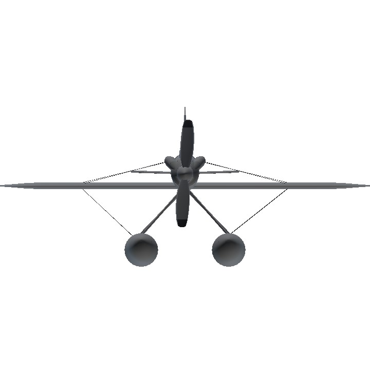
The fuselage of the S.5 was entirely composed of metal, primarily duralumin; the strength of this material enabled the use of semi-monocoque construction, an arrangement that substantially reduced the amount of space taken up be the fuselage. In turn, the cross section of the fuselage could be minimised, to the extent that the pilot was seated on the floor of the fuselage while their shoulders were in contact with the metal skin of the fuselage. Structural elements within the fuselage included loosely-spaced flat U-section formers throughout its length that worked in conjunction with the skin, which functioned as longerons within the stress-resisting structure; in key areas, it was reinforced using fore-and-aft stringers. The forward section of the fuselage had particularly strong frames in order to appropriately support the wing roots, undercarriage struts and function as the attachment point for the anti-lift wire bracing. The latter feature was particularly crucial to the stability of the bracing of both the wings and the sizable floats fitted.
The aircraft was fitted with single-step floats; their structure comprised central longitudinal bulkheads that directly attached to the transverse frames. Several of the longitudinal members were placed between the frames. They were almost entirely composed of duralumin, the centre section of the starboard float was made of steel to permit it to support the primary fuel tank. As there was no room for a fuel tank within the fuselage, all of the aircraft's fuel was carried within the starboard float, which was 8 inches (20 cm) closer to the aircraft's centreline than the port float; this arrangement gave the aircraft a lower centre of gravity as well as helping to offset engine talk.
Largely due to a lack of available experimentation time during the aircraft's short development window, the use of an all-metal wing was discounted. Instead, proven wooden construction was used for the wire-braced wings, which possessed spruce spars, spruce-ply ribs and a smooth plywood covering. They were built in two halves along a conventional twin-spar arrangement, albeit with a diagonal member between the wing tips and the fittings for the streamlined bracing wires which stiffened the wing against torsion and reduced the likelihood of encountering aeroelastic flutter. Large radiators were present on the wings; positioned tightly against the wings, they were of a relatively low weight as to avoid incurring excessive wing loading.
The engine was cooled via a somewhat unusual arrangement, using radiators located on the wings in place of the Lamblin type radiators of the S.4; these radiators were made up of corrugated copper sheets and covered a large proportion of the wing surface. Particular attention was paid to the oil system with the aim of minimising fractional losses in the propeller gearing and maximising the aircraft's speed potential. As traditional arrangements were deemed to be insufficient, the oil was cooled via a series of corrugated steel radiators positioned on either side of the fuselage; further cooling of the gears themselves was achieved via several opening in the cowlings of the cylinder block.
The forward bottom portion of the fuselage was reinforced using laminated duralumin to function as the engine bearer, comprising two primary box section bearers that were secured to cradles. One advantage of the scoop-formed engine mounting was a relatively high level of accessibility to the engine. The engine itself was cleanly faired into the fuselage to maximise aerodynamic efficiency.
The flight controls were of a conventional nature, lacking any implementation of variable gearing except for in the actuation of the ailerons. The aircraft was considered to be relatively easy to handle considering its relatively high top speed for the era. The horizontal tail surfaces, which were made of wood, had their control cranks housed within the stern portion of the fuselage; the cranks for the elevator were intentionally offset so they would sufficiently clear the rudder post.
A total of three aircraft were built, one with a direct drive 900 hp (670 kW) Napier Lion VIIA engine, and the other two with a geared 875 hp (652 kW) Napier Lion VIIB engine.
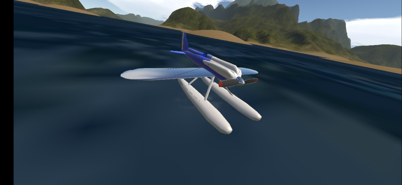
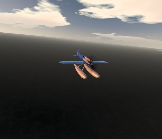
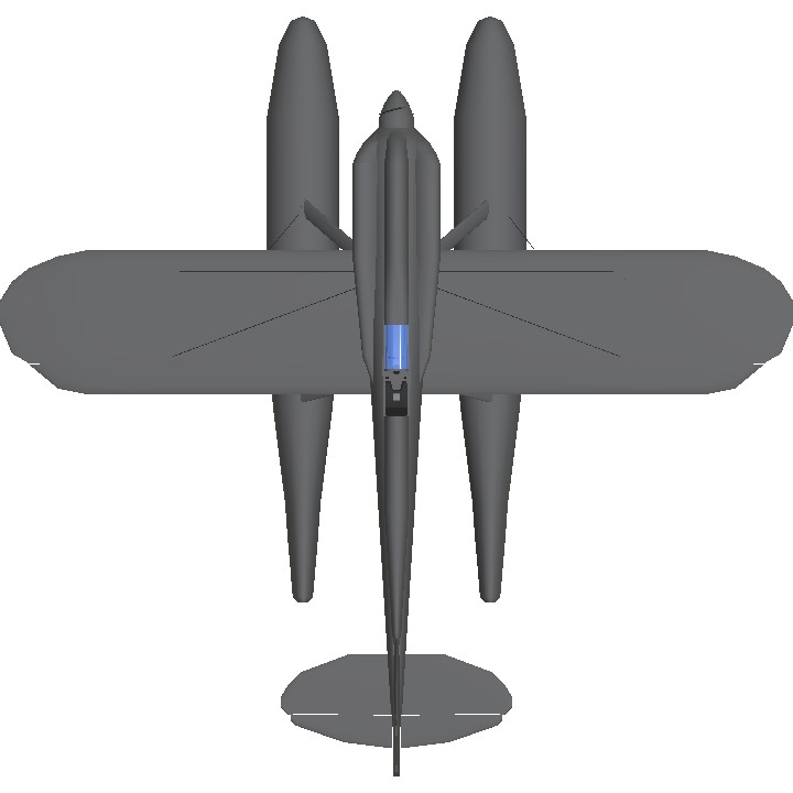
image gallery
Controls:
Ag1:canopy
Ag8:gyroscope, don't turn off (it's a warning)
If you find any errors or defects, let me know so I can correct them.
have fun
Specifications
General Characteristics
- Created On Android
- Wingspan 27.1ft (8.3m)
- Length 26.0ft (7.9m)
- Height 12.0ft (3.6m)
- Empty Weight N/A
- Loaded Weight 3,238lbs (1,468kg)
Performance
- Power/Weight Ratio 2.81
- Horse Power/Weight Ratio 0.277
- Wing Loading 5.5lbs/ft2 (26.8kg/m2)
- Wing Area 589.3ft2 (54.8m2)
- Drag Points 2140
Parts
- Number of Parts 168
- Control Surfaces 0
- Performance Cost 673
@crazyplaness Could you help me, I made this aircraft for a challenge but it didn't go into automatic credit.