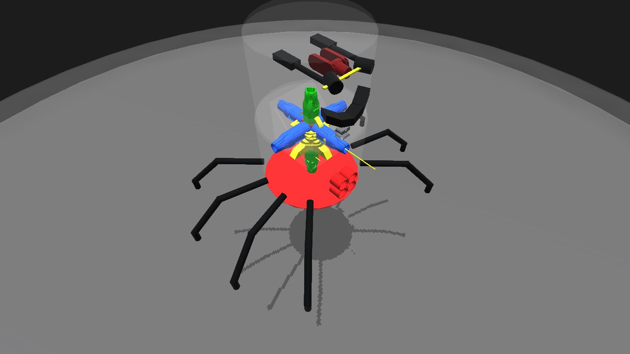
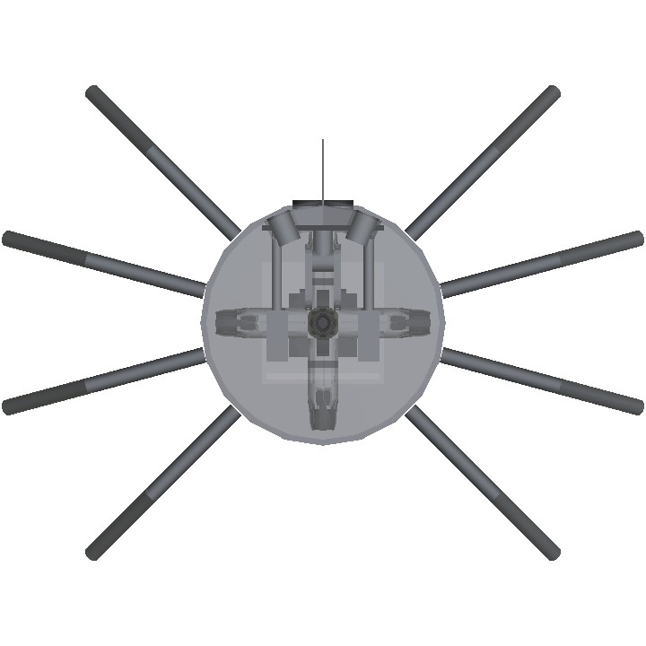
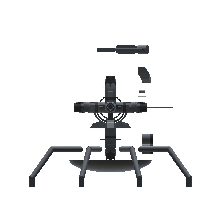
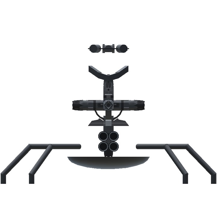
Experiment: to fix various flaws with the previous design, like accuracy and reliability
Body: dead meme that's so dead it's basically necromancy
Result: actually good
Active parts: 10
Update2005231812: The Speed Limiter now has an alternative code that uses in-game speed variables, instead of in-game coordinates. This allows control based on IAS or TAS. Effect remains unchanged if using GS.
Demo video (old: speed limits are different)
View: SimplePlanes | YouTube
This version overhauls the propulsion system to a more reliable one. No function crashes, no movement in the wrong direction.
USES:
- Mecha
- Other machines with 2D/3D shooter gameplay
- Arcade-style handling
- Belkan witchery
- May be adapted for realistic uses like drones and hovercraft
CONTROLS:
Pitch - Strafe forward/backward
Roll - Strafe sideways
Yaw - Yaw
VTOL - Vertical speed control
Trim - Gun elevation
LandingGear - Change ground detection limiter mode
Activate8 - Master control
Defined maximum horizontal speed: 85 m/s
Defined maximum vertical speed: 70 m/s
Defined speed variable: GS or coordinate-type system
Notes:
- Without changing altitude, a horizontal speed of 85 or 90 m/s allows for easy dodging of stock destroyer missiles. 80 m/s will require skill.
- Horizontal speed is completely separate from vertical speed on this aircraft.
USAGE NOTES:
- The line of action of all parts should pass through or near the center of mass.
- The aircraft should not have wings with wing physics.
- The aircraft can have any amount of mass, but engine power must be changed accordingly.
- Be sure to include a sufficient number of inlets.
Demonstrator: pow() function input non-linearity
Shows how different exponents interact with numbers. In the aircraft's inputs, x is a data input clamped between 0 and 1, and usually multiplied by a standard player control. It may be a substitute for PID() or ternary functions.
Example:
INPUT * pow( clamp01(1 - V/VMAX) , EXP )
INPUT is a user input
V is a variable for velocity (GS/IAS/TAS), possibly with other additional functions
VMAX is a defined maximum speed
EXP is an exponent greater than 1 (see graphs). Alternatively, remove the 1 - and use an exponent between 0 and 1.
Funky Trees
Detailed information on parts used in the machine. Be sure to check the type of settings used in each part.
Blue Section
The blue parts are responsible for main horizontal control.
Forward Engine
clamp01(Pitch) * pow(clamp01(1 - (GS*cos(abs(AngleOfSlip)))/85), 0.1)
Backward Engine
clamp01(-Pitch) * pow(clamp01(1 - (GS*cos(180-abs(AngleOfSlip)))/85), 0.1)
Leftward Engine
clamp01(-Roll) * pow(clamp01(1 - (GS*cos(-AngleOfSlip-90))/85), 0.1)
Rightward Engine
clamp01(Roll) * pow(clamp01(1 - (GS*cos(AngleOfSlip-90))/85), 0.1)
Finds the velocity of the aircraft in the direction the respective engine is facing in (i.e. in the aircraft's local X or Z axis), and uses the power function to roll off the input as velocity reaches the defined limit.
The engines do not work in pairs/groups, but have similar codes.
Resultant horizontal speed is controlled by a different engine.
Green Section
The green parts are responsible for vertical control.
Note: the PID functions are split for clarity. The second line is the target variable, the third line is the feedback variable. The fourth line shows the error gain values P, I, and D, and are not tuned.
Upward Engine
clamp01(PID(

VTOL+(LandingGear?(5-clamp(AltitudeAgl,0,5))/10:0),

rate(Altitude)/min(LandingGear?70:1+AltitudeAgl*5+clamp01(sign(VTOL))*70, 70),

1000, 1, 1))
Downward Engine
clamp01(PID(

-VTOL-(LandingGear?(5-clamp(AltitudeAgl,0,5))/10:0),

-rate(Altitude)/min(LandingGear?70:1+AltitudeAgl*5+clamp01(sign(VTOL))*70, 70),

1000, 1, 1))
Takes the user input into a PID controller, and causes the aircraft to match a target vertical speed. The engines work together, and have very similar codes.
When LandingGear is FALSE (extended), causes the aircraft's possible downward velocity to decrease near the ground. The effect is the aircraft accelerating upwards when falling towards the ground, and possibly landing smoothly. This code is in the feedback variable.
When LandingGear is TRUE (retracted), causes the aircraft to stay at least a fixed distance (5m AGL) from the ground. This is used to counteract the problem that the machine descends slowly in flight, noticeable when near the ground/water. The user input can reduce the minimum altitude AGL. This code is in the target variable.
Yellow Section
The yellow parts are other movement controllers.
Gyroscope Yaw
clamp(PID(Yaw, YawRate/200, 1, 0.05, 0.03), -1, 1)
Maintains a set yaw rate. Unchanged from previous version.
Movement Direction Tracker
smooth(AngleOfSlip/180, (GS<10 ? 0 : 1000))
Rotates the Automatic Airbrake and Speed Limiter to face the aircraft's direction of movement. Additionally rotates a visual indicator visible from external cameras.
Automatic Airbrake
sqrt(pow(Roll,2)+pow(Pitch,2)) > 0.03 ? 0 : 1
Slows down the aircraft if the combined joystick input is too small. Customizable deadzone.
Speed Limiter
pow(clamp01( sqrt(pow(rate(Longitude),2)+pow(rate(Latitude),2)) / 85), 400)
Opposes the blue engines if the horizontal speed (calculated using global axis methods) is greater than the defined limit. Responsible for preventing a speed hack. As a side effect, also causes the flight direction to match the joystick's direction, so a separate system need not be designed.
Alternative code:
pow(clamp01( abs(GS*cos(AngleOfAttack)) / 85), 400)
This method is functionally the same if using GS, but now provides the ability to use IAS or TAS. As such, it is better.
Specifications
General Characteristics
- Predecessor !rds2b(85)
- Created On Android
- Wingspan 8.6ft (2.6m)
- Length 6.4ft (2.0m)
- Height 6.0ft (1.8m)
- Empty Weight 5,002lbs (2,269kg)
- Loaded Weight 5,511lbs (2,500kg)
Performance
- Power/Weight Ratio 4.281
- Wing Loading 4,096.3lbs/ft2 (20,000.0kg/m2)
- Wing Area 1.3ft2 (0.1m2)
- Drag Points 161
Parts
- Number of Parts 59
- Control Surfaces 0
- Performance Cost 203


DeSpAcIto
@AstleyIndustries thanks
@NotFinn55 yes, you can use/refer to the codes if you like
@AstleyIndustries Pretty cool, could I experiment with the mechanics of it for a design I’ve been thinking of?
@An2k
.
Most people do, but it's fairly pointless to do so normally because FT expressions are usually specifc to the craft. Instead, what really helps others is creating a general form of a system, like he did with the Desmos widget, but it take more effort and most don't have the time to spare.
Awesome ...wished more builders should put FT codes on description like this for others to study...btw sometimes I get confused on which direction the craft is facing when I fail to notice the orientation legs or the face on craft..other than that love the build and the complex PID & FT codes.. wish i understand much more
This is why mobile suit gundam is complex